

Chris Soranno, Manager of International Safety Standards at SICK, answers common questions about the new guidelines for separation distance standards
Guards and protective devices must be securely installed and located at a distance where recognized hazards cannot be accessed by affected persons if they reach over, under, around or through a safeguard.
The guidelines for calculating these minimum separation distances have traditionally been different between North American and International markets. However, recent changes to standards drastically reduce these differences and better align both the methodology and the calculated results for separation distances.
If you’d like to watch our webinar about the new requirements for separation distances of guards and protective devices, please view that here. In this blog post, we’re recapping some of the questions we received at that webinar, answered by our industry expert Chris Soranno, Manager of International Safety Standards at SICK.
What have you found is the best tool to measure machine stopping time?
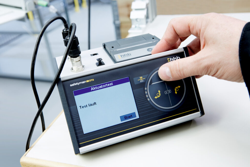
A: There are a few commercially available tools on the market specific for use in measuring machine/system response time for safety-related applications. I am aware of products from hbb Electronic and Gemco Ametek. Both have linear transducer and rotary encoders for capturing different types of hazardous motion. Some of these devices may provide the results of the calculation for separation distance onboard the device, but given the recent changes to the standards, it is possible that manual calculation according to the new guidance may still be necessary.
SICK works closely with hbb Electronic, and also uses their device when performing Stop Time Measurement Services for customers. Please keep in mind that these devices need to be frequently calibrated to ensure accurate and precise results.
Annex B of ISO 13855:2024 also provides informative guidance on the methodology for the measurement and calculation of system performance. Annex J of ANSI B11.19-2019 (R2024) provides similar guidance.
Some on the webinar mentioned the use of a high speed camera, noting that the data is recordable and can be stored in the construction file in case of an audit, but also noted that it can be hard to get actuation (trigger condition) and the hazardous motion within the same field of view.
I’ve conducted several measurements of machine response time using a camera, and the points made are correct. In addition, other considerations to account for include:
- Understanding the relationship between the LED indicator on the protective device and the output (e.g., OSSDs). There is no standard for this, so it is always best to check with the manufacturer for documentation to determine if the visual indicators LEAD or LAG the actual signal to the safety-related parts of the control system.
- Regardless of camera speed, you may find that it is still difficult to determine when the condition has changed that you are manually trying to observe. I have seen this firsthand on both sides of the equation:
- I have seen LED indicators take up to 3 frames to go from an OFF to an ON condition; in this case, it is always best to err on the conservative side and select the earliest frame.
- Depending on the machine / application, it may be difficult to determine when the hazardous condition (typically a motion) has achieved the intended risk reduction. This is often – but not always – a complete stop of the motion. However, I have also experienced applications where the mass of the tooling appears to ‘bounce’ or oscillate at the end of the motion. Determining when “hazardous” motion has ceased (versus “all” motion) is again somewhat subjective.
- The axis of motion relative to the viewing angle. In applications where motion occurs multi-dimensional (e.g., robotic applications), there is also a concern that the hazardous motion to be evaluated could be traveling in the Z-axis (directly toward or away from the camera lens). When the motion trajectory is nearing completion, the slight change of size in the frame makes exact determination very difficult. For this reason, I have used multiple cameras (with the same frame rate) positioned at slightly different angles to avoid motion in the Z-axis.
- Another consideration with the camera-based approach is that each frame is only capable of capturing an instant in time. There is the possibility that the condition change you are looking for began immediately after the previous frame, but not captured until the next frame. To account for this in a conservative manor, at least 1 frame (if not more) should be added to any calculation. The use of multiple cameras also helps validate the results.
When in doubt, I strongly suggest partnering with an experienced service provider with established procedures who can draw upon years of experience with a variety of machinery types and to help.
Is it recommended to install the safety sensors inside the guards to prevent the openings before the trigger point?
A: Whenever possible, it is always best practice to implement design measures to reduce (or even eliminate) the amount of intrusion beyond the safeguard before triggering the safeguard.

Until when we can still use the 2010 version?
A: In the United States, the 2010 edition of ANSI B11.19 was withdrawn upon publication of the 2019 edition. In the Foreword of the new standard, the B11.19 Subcommittee recommended that the new standard be considered for implementation within 30 month of its approval date (11 October 2019) – meaning no later than 11 April 2022. However, all standards are voluntary.
Internationally, the new (2024) edition of ISO 13855 can be used immediately since it represents current state-of-the art in the market. In Europe, however, the 2010 edition is currently still listed in the Official Journal of the European Union (OJEU), meaning it can be used for a presumption of conformity with the Essential Health and Safety Requirements (EHSRs) of the Machinery Directive (2006/42/EC). [NOTE: this Directive will soon be replaced by the Machinery Regulation (EU) 2023/1230, which takes effect on 20 January 2027.] There is no announcement yet when ISO 13855:2024 will be harmonized in Europe, but the standard was developed under the CEN process necessary to achieve harmonization.
Typically, newly harmonized standards take effect 24 months after being listed in the OJEU. Once included in the OJEU, the list with also include relevant dates for “valid as of” and “retracted as of”; in some cases, both predecessor and successor editions may be listed in parallel for a period of time. Regardless of a standard’s status in the OJEU as a harmonized standard, both the Machinery Directive (Clause 9.2) and the Machinery Regulation (Clause 7.3) state that machinery manufacturers have the ongoing responsibility to meet the corresponding state-of-the-art. Therefore, best practice is to adopt the requirements of these new standards as soon as possible.
Is there guidance to include the time it takes a person to open a gate (instead of breaking a presence-sensing device) when calculating safe stopping distance?
A: The current standards [ISO 13855:2024 and ANSI B11.19-2019 (R2024)] do not consider the time to manually open an interlocked guard. However, ISO 13855:2024 does address the opening time associated with power-operated guards (t3), and allows this value to be reduced from the overall response time T. This is only applicable to power-operated guards, defined in ISO 14120:2015 as a “movable guard that is operated with the assistance of power from a source other than persons or gravity.” Therefore, this consideration specifically excludes manually operated guards.
Are the standards intended to be retroactive? Has OSHA adopted the new measurements?
A: All standards are voluntary. While ISO standards typically only address requirements for new equipment placed on the market (in the future), most ANSI standards address all machinery in the market (including existing equipment).
However, the Foreword of ANSI B11.19 identifies that the Subcommittee recommends:
- that suppliers complete and implement design changes for new machines and machinery systems within 30 months of the approval date of this standard
- that users evaluate whether existing machinery and machinery systems have acceptable risk within 30 months of the approval date of this standard using generally recognized risk assessment methods. If the risk assessment shows that modification(s) is necessary, refer to the requirements of this standard or the machine-specific “base” safety standard to implement risk reduction measures (protective measures) for appropriate risk reduction.
The approval date of the document was 11 October 2019, so 30 months later would be 11 April 2022.
As stated in the Effective Date guidance above, a new standard does not automatically imply every existing machine must be immediately updated. Instead, a logical approach should be taken; if a risk assessment identifies that the current residual risk is inadequate, then any modifications should be done to the current standard(s) defining state-of-the-art.
Furthermore, only OSHA 29 CFR 1910.217 has requirements for “safety distance,” and this regulation is limited in scope to mechanical power presses. The guidance for “safety distance” provided in this regulation only addresses:
- presence sensing point of operation devices (c)(3)(iii)
- two hand controls (c)(3)(vii)
- two hand trip devices (c)(3)(viii)
For each of these devices, the OSHA approach is a simple formula:
Ds = 63 inches/second × Ts
(63 in/s ≈ 1600 mm/s)
When compared to the current approach (or even the approach recommended in standardization for the past 35 years), we see that the general concept of “reaching distance” (DDS) is not even accounted for by the OSHA formula, let alone the newest addition of the “supplemental distance factors” (Z). These updates have redefined state-of-the-art in response to significant hazards that have been encountered in the workplace.
This regulation has not been updated since first promulgated in 1971 under the OSH Act, so the new considerations described in the webinar for determining separation distances according to current best practices and state-of-the-art have not ‘officially’ been adopted. However, it’s also important to point out the OSHA General Duty Clause requires that “each employer shall furnish … a place of employment which are free from recognized hazards.” Considering the obligations to employers in combination with the reason why industry standards are continuously updated, it’s clear that the best approach to worker safety is to utilize the most current standards available.
Is the standard concerned with (or does it address) someone else resetting the SRMCD when someone is past the presence-sensing device? Or is this addressed solely by the concept of “qualified/competent” personnel?
A: The guidance for determining reaching distance to a safety-related manual control device (SRMCD) in both ISO 13855:2024 and ANSI B11.19-2019 (R2024) only addresses the issue of reaching the SRMCD from within the safeguarded space (presumably by the operator or exposed individual). For many years, standards and regulations have required that certain control devices be located such that they can only be actuated from outside the safeguarded space (e.g., Directive 2006/42/EC, Clause 1.2.2; ISO 11161:2007, Clause 8.9; ISO 16092-1:2018, Clause 5.4.1.1.3; ISO 13849-1:2023, Clause 5.2.2.3). The new content in the ANSI B11.19 and ISO 13855 standards now provide verifiable guidance to determine if this requirement is met.
However, there is still the concern that another person may actuate an SRMCD when the operator(s) is already inside the perimeter safeguarding system. This is a concern when whole body access exists, defined as the “situation where a person can be completely inside a safeguarded space”. A good risk assessment process should identify this possibility, since both ‘intended use’ and ‘reasonably foreseeable misuse’ must be address – where ‘reasonably foreseeable misuse’ includes use of a machine in a way not intended by the supplier/user, but which may result from readily predictable human behavior.
Additional guidance is available for these applications, including ANSI B11.19-2019 (R2024), Clause 9.11, as well as a new ISO standard currently under development: ISO 12895 title “Safety of machinery — Identification of whole body access and prevention of associated risk(s).”
What are the correct heights when using 2, 3 or 4 beam perimeter guarding? Can 2 beam be used at 200mm and 400mm? Do all 2 beam safety devices require 500mm between the beams?
A: All of Annex C in the new ISO 13855:2024 is applicable for determining the height of multiple (or arrangement of separate) beam devices when the effective detection capability is greater than 120mm. This Annex is normative and is limited to applications without change of elevation. The information provided is based on the number of beams in the arrangement, and the Annex provides two separate tables: Table C.1 includes the default values, and Table C.2 provides alternative heights for industrial applications where allowed by a risk assessment.
The requirements of Table C.1 are as follows:
- 2 beams: 200 & 400 mm from the reference plane
- 3 beams: 200, 600 & 1000 mm from the reference plane
- 4 beams: 200, 500, 800 & 1100 mm from the reference plane
For the heights above to be effective to detect entry of the human body into the safeguarded space, it is also important to evaluate the restrictions relevant to the openings being safeguarded by the multiple beam devices. While the 3- and 4-beam applications have no restrictions, the values listed above for 2-beam devices are only valid if the height of the opening is less than or equal to 600 mm.
There are different requirements for 2-beam configurations if there is a change in elevation of more than 300 mm. In this case, ISO 13855:2024, Clause 8.3.5 provides additional restrictions on:
- the width of the elevated surface (less than or equal to 50 mm)
- the height of the lowest beam from the higher surface (equal to 200 mm); and
- the height of the highest beam from the lower surface (greater than or equal to 900 mm)
To summarize the guidance for 2-beam devices according to the new ISO standard, the appropriate applications are either:
- No change in elevation (or change ≤ 300 mm):
- the first beam is 200 mm above the reference plane, AND
- the second beam is 400 mm above the reference plane, AND
- a maximum opening height of 600 mm
OR
- Change of elevation > 300 mm:
- the first beam is 200 mm above the higher (step) surface, AND
- the second beam is ≥ 900 mm above the lower surface, ANDbeam spacing ≤ 500 mm, AND
- width of the elevated surface step is ≤ 50 mm
If your question was in regard to the updated American standard, ANSI B11.19-2019 (R2024), Clause 10.7.2 addresses the requirements for light curtains and single/multiple beam devices. This standard states that the lowest beam cannot be more than 300 mm above the reference plane, and the spacing between any subsequent beams (regardless of number of beams) cannot be greater than 600 mm.
Any guidance for gaps to prevent reaching between a fixed surface and optoelectronic guard?
A: Both ISO 13855 and ANSI B11.19 address the consideration of reaching around a detection zone of an electro-sensitive protective equipment (ESPE) or presence sensing device (PSD), respectively. As addressed in the standards, this is considered ‘reaching under a vertical detection zone (sensing field)’. Guidance is available in ISO 13855:2024, Clause 8.4 and ANSI B11.19-2019 (R2024), Annex I.3.3.
We covered this very briefly in the webinar (see discussion of slide 26). Essentially, if the detection zone is close enough to the surface to detect finger/hand/arm access, then the same (or similar) formula can be used as if the person is reaching through the detection zone. However, if the detection zone is far enough away from the fixed surface that the entire arm could enter before detection, then a simple table is provided to describe the possible reaching distance to account for in the overall separation distance calculation.
Are there cases where separation distance does not apply to a safeguard?
A: Yes, there are! The separation distance concept is applicable to any safeguarding technique where the safety function:
- includes initiating a protective stop to the hazardous machine function, or
- is intended to prevent hazard zones from being reached during the hazardous condition(s) of the equipment
As used in the presentation, the term “separation distance” is inclusive of:
- ‘minimum distance’ as discussed in previous versions of ISO 13855 for protective devices
- ‘safety distance’ as considered in the current version of ISO 13857 for guards and protective structures
- ‘safety distance’ as addressed in many North American standards, including ANSI B11.19, applicable to all engineering controls (both guards and devices)
There are other safety functions where the intent is simply to maintain an acceptable level of risk reduction. For instance, presence sensing function uses sensitive protective equipment (SPE) or presence-sensing devices (PSD) to detect presence of a person inside a safeguarded space (known as “whole body access” applications) purely to prevent restart. In this application, the detection zone is not initiating a protective stop (only maintaining the stop condition), and therefore the separation distance considerations do not apply.

It’s great to see that both standards are now more aligned than they were before, but how do we decide which one to use in the instances where there are still different approaches?
A: One consideration is to evaluate the market expectations for the region where the machinery will be installed and operated. However, machine users may have a specific requirement according to company policies. When no requirements are specified, we must also recognize that standards are voluntary, meaning designers can choose whether to follow them at all. In Europe, this is a bit more complicated since harmonized standards (proven to meet the Essential Health & Safety Requirements of the Machinery Directive) can be used for the conformity assessment before applying a CE mark – but there are still other ways to prove compliance with the EHSRs for CE marking.
Furthermore, both standards are based on the current state-of-the-art and scientific process available at the time – and there are no known reported cases of injury when either standard has been applied as intended.
Essentially, if good due diligence is applied and all conditions and considerations have been documented, either approach can be applied – in theory. However, market demands (from customers, inspectors, authorities, etc.) may establish a preference, in which case further consideration may be required.

When or how would a designer choose to calculate or measure the overall system response time T?
A: When all the individual response time values of a safety function are known, it is best practice to use these values. These stated values are determined by the component supplier and should account for ‘worse case’ conditions. On the other hand, if data is unavailable for some individual components, then measurement is the best way to determine the response times.
However, a measurement is only a snapshot in time, indicative of the status at the time the measurement is taken. For this reason, both the ANSI and ISO standards recommend adding an additional factor (tF in ISO, Tscm in ANSI) to account for the eventual degradation / deterioration in performance of components (e.g., due to wear, ageing, temperature, etc.). The larger this factor is, hypothetically more time can pass before another measurement is required – but a larger value for this factor will result in a larger separation distance, costing floor space and possibly increasing incentive to defeat or bypass the protective measure. Conversely, a smaller factor can be use, but frequency of the measurement must increase accordingly. In some cases, type-C standards provide guidance for a fixed value (of the factor and/or the frequency of inspection), whereas other type-B standards (like IEC 62046) recommend a minimum factor of 10% (of the total measured time) – but there is no correlation provided regarding how this value is associated with the frequency for performing measurements.
Is ‘dynamic separation distance’ applicable to AGV, industrial trucks, mobile robots, etc.?
A: Both standards (ISO 13855 and ANSI B11.19) are type-B standards – meaning they deal with one safety aspect that can be used across a wide range of machinery. However, when a type-C standard (machine specific standard dealing with detailed safety requirements for a particular machine or group of machines) exists, AND when that type-C standard deviates from one or more technical provisions dealt with by a type-B standard, the type-C standard takes precedence. So if a type-C standard exists (e.g. ISO 3691-4 & ANSI/ITSDF B56.5 for driverless industrial trucks) and it provides different guidance, then the guidance for the specific machine type is to be applied.

Does SICK offer a service to help end users comply to the new ISO 13855 or ANSI B11.19 guidance for separation distances?
A: SICK offers a number of Safety Services, including Stop Time Measurement using calibrated equipment to ensure accurate and precise results.